18 Pulse Vfd Wiring Diagram
Filtration and inversion back to ac. (1) the vfd's three phase ac input terminals (r/l1, s/l2, t/l3) the power line's input terminals connect to 3 phase ac power through line protection or leakage protection breaker, it does not need to consider the connection of phase sequence.

What are leading methods for VFD control of AC motors?
Main circuit wiring variable frequency drive wire input to terminals l1, l2 and l3 for three phase input.

18 pulse vfd wiring diagram. Vfd start stop wiring diagram: The variable frequency drive (vfd) system shall contain all components required to To comply with regulations, different solutions should be considered;
Make sure to connect the ground terminal to an appropriate safety ground. The phase shift transformers required shall be factory wired and mounted within the vfd enclosure as an integral part of the vfd assembly. • encoder a/1 and b/2.
It reveals the components of the circuit as simplified forms and also the power as well as signal connections in between the gadgets. Both systems can be effective at mitigating harmonic All power and control terminations and termination strips shall be identified in accordance with all schematics and wiring diagrams.
Vfd is a short form of variable frequency drive or variable voltage variable frequency drive.the vfds are working based on changing the input frequency and input voltage of the motor, we can change. Transformers external to the vfd enclosure are not acceptable. Filters (each would require field mounting and wiring).
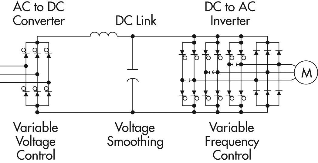
In an ac drive there are two additional stages: The vfd is to be supplied with a transformer to provide phase shifting for a clean power 18 pulse or higher converter bridge. Learn the basic wiring of variable frequency drives / vfd with our electrician steve quist.
In this video, we used the very popular mitsubishi d700 series vfd, showing single phase and three phase wiring instructions. What is pulse number (6, 12, 18, 24) in drives? We strongly recommend using a certified electrician.
The drive has terminals available to connect a dc link choke. I am here with giving you a vfd start stop wiring diagram for running a vfd through panel board push button and keypad of the vfd (it is called hmi). The vfds showed in the video are the d720s (230v single phase) and the d720 (230v three phase).
Vfd package cost would double, wall space would increase to 185% and total line current savings would be less than 3%. This diagram shows the wires that supply power to the vfd the wires that provide voltage from the vfd to the motor and all the necessary input and output signals that the vfd needs for operation. Pulse a/1 leads as diagrammed below for encoders with pulse 2 leading, change diagram for these connections:
In variable speed drive (vsd) systems, both ac and dc, the first stage of power conversion is from ac to dc. This was done to formulate a direct comparison to the matrix ap filter. Main circuit wiring the vfd main circuit terminals shown as below figure.

Retrofit 18 Pulse VFDs EMA Inc.
![]()
Line voltage and current of 18 pulse rectifier for 432V output voltage Download Scientific Diagram

(PDF) A hybrid 18pulse rectification scheme for diode front end Variable Frequency Drives
motor Does this type of Dual Voltage AC Drive exist? Electrical Engineering Stack Exchange
(b) Threelevel capacitorclamped inverter with 18pulse input... Download Scientific Diagram
![]()
18 pulse star connected autotransformer. Download Scientific Diagram
FAQ What is a pulse rectifier and what kinds are there?


Measured 18pulse VFD current waveform Download Scientific Diagram

Schematic representation of a traditional 18pulse converter circuit. Download Scientific Diagram
![]()
Winding connection diagram of the proposed autotransformer for 18Pulse... Download Scientific

Supply system on the basis 18pulse diode rectifier with coupled... Download Scientific Diagram
![]()
18Pulse Drive with 3 transformers [11] Download Scientific Diagram

Medium voltage industrial variable speed drives Part 2 EE Publishers
Principles of Operation AC VFD Drives

VariableFrequency Drives Instrumentation
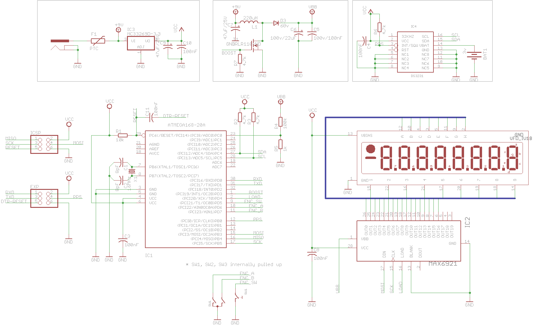
The TC18 My IV18 Based VFD Tube Clock

Two 700HP 440V Cooling Water Pumps in a Power Plant. These are 18pulse... Download Scientific
![]()
Schematic of windmill type 9phase autotransformer for 18pulse drive [15] Download Scientific

Matlab/Simulink model of 18 pulse rectifier. Download Scientific Diagram